
Reflective beam shaping · 2026-10-06
Cylindrical and toroidal mirror
Different curvatures in two directions for laser beam shaping and spectroscopy experiments.
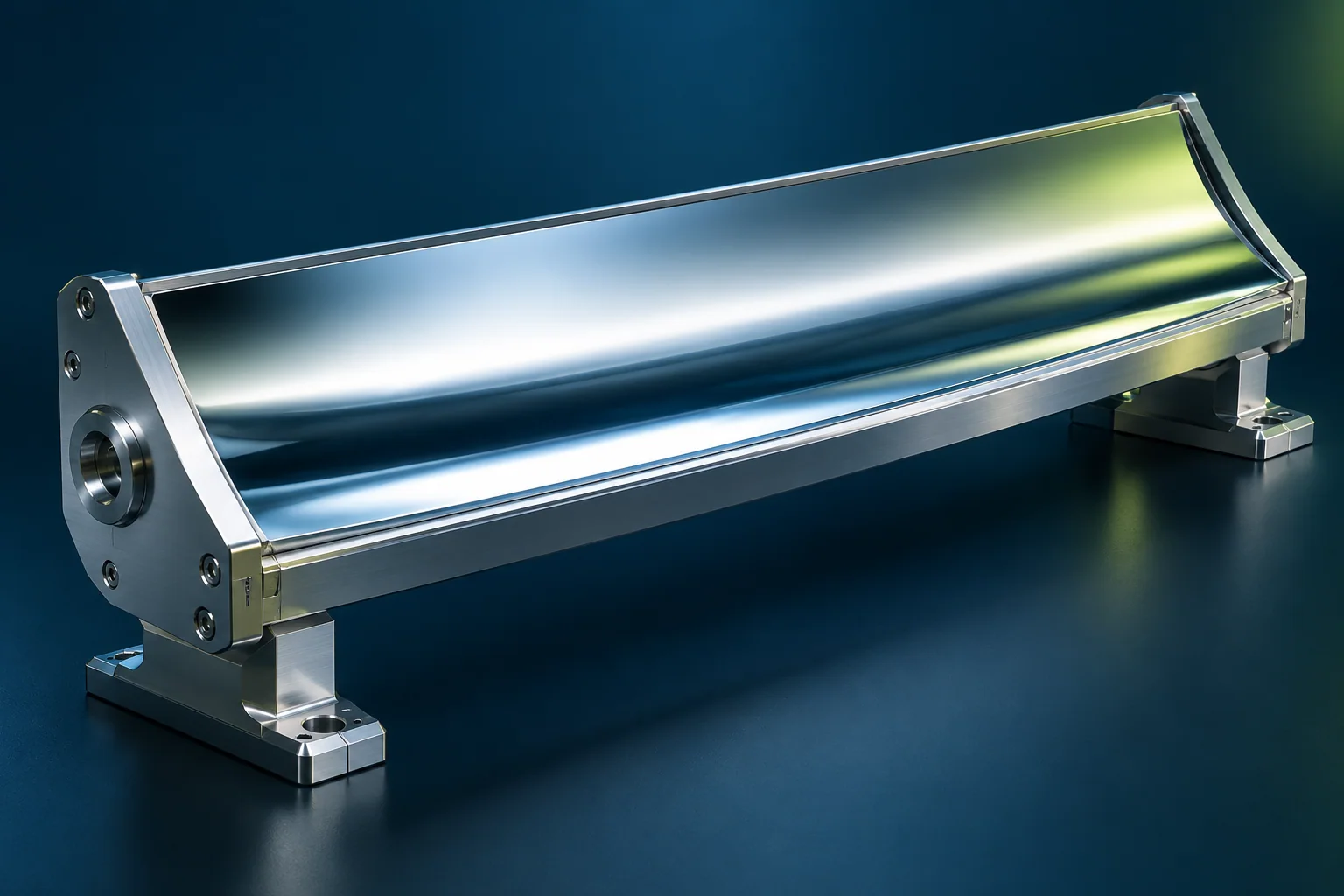
AI-generated engineering concept · Not to scale; not a manufactured component or measurement result.
FROM CONCEPT TO YOUR COMPONENT
Start with the function, material and the question your first trial should answer.
Why work with us? Two curvature directions, one defined mounting orientation.
A surface matched to the beam
With IL600 freeform machining, we plan the two principal curvatures and usable mirror zone together. This matters for non-axisymmetric tasks where catalogue curvatures or available rectangular apertures do not fit.
Fixturing effects are part of the trial
On an elongated mirror, clamping and stiffness can affect the surface. We agree fixturing and the assessment condition in advance, so the next iteration is more than trying another surface equation.
Geometry documented for integration
We tie the surface directions to mounting datums. The resulting documentation supports system alignment as well as part inspection; focus and beam-shape performance must be checked in the final arrangement.
The task · different focusing in different directions
This concept describes a reflective element with different curvature along its principal directions. A cylindrical surface acts along one direction; a toroidal surface uses two curvatures to shape the beam. Geometry selection belongs in the optical system model.
Engineering data · curvatures and mounting orientation
Define principal directions, curvature descriptions, active surface, incidence geometry and mounting-face orientation. The drawing distinguishes assembly datums from those used for surface evaluation.
A manufacturing route for a rectangular mirror
The surface may not follow a rotationally symmetric profile. Freeform toolpaths, the pre-machined blank and workholding jointly establish the operation sequence. For an elongated component, stiffness and clamping-induced deformation also belong in the trial plan.
Comparison with the design model
Evaluate both principal directions and the complete active region. The installed focus or beam shape requires mounting and functional testing as well as geometric conformity.
a reflective trial component, datum-based form evaluation and mounting feedback.
The application behind the component.
Review the operating requirements and related engineering tasks in these application areas.
CONNECTED ENGINEERING
Different challenges. Different geometries. Shared precision.
- 01Function
- 02Geometry
- 03Application
Conceptual illustration of our engineering approach.
THE NEXT STEP
Let’s talk about your next component.
Tell us about its function, material and critical engineering question. Together, we can define a feasibility review or a focused first trial.