← Applications

Laser research and industrial optics

Laser optics and beam shaping

Reflective optics, axicons and freeform surfaces for laser systems — connecting the target beam profile with machining and inspection planning.

By individual engineering agreement
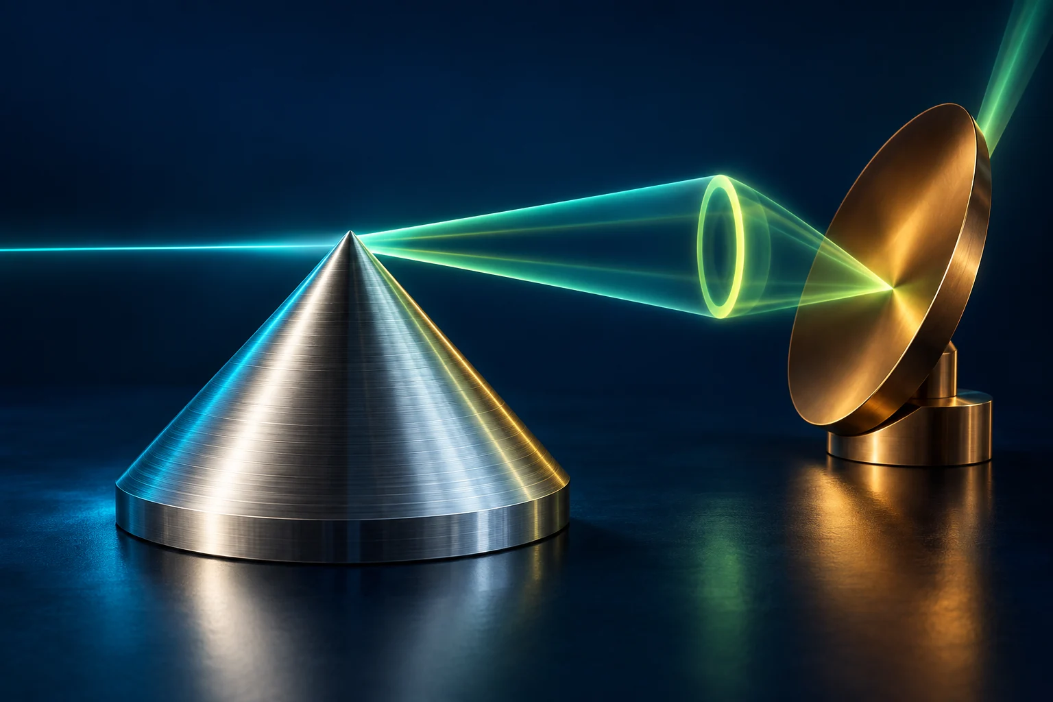
Laser optics and beam shaping — illustrative visual, not measurement data

AI-generated engineering concept · Not to scale; not a manufactured component or measurement result.

Start with the beam, rather than the shape of the part

A focused spot, line, ring and approximately uniform illuminated area require different surfaces. The starting point is the incoming beam and the plane in which the intended distribution must be achieved. Geometry serves this function.

Laser material processing, spectroscopy, microscopy and research optical systems can all involve a focused component-development task. Optical-system design, component manufacturing and verification of performance are agreed as separate work packages.

Three component families with different development questions

Reflective focusing and beam-steering elements: off-axis parabolic, cylindrical or toroidal mirrors. Mounting, optical-axis orientation and mechanical datums matter alongside surface form.

Axicons and conical surfaces: geometries to investigate for ring-shaped or Bessel-like beams. Tip condition and transition regions deserve particular attention; the usable range depends on the optical arrangement.

Freeform beam shapers or replication masters: surfaces developed for a target intensity distribution. A top-hat profile is not a property of the machined component alone: it must be evaluated with the input beam and complete system.

The IL600 within the manufacturing route

Diamond turning can address rotationally symmetric profiles, while five-axis and Overdrive-assisted machining can address direction-dependent and freeform surfaces. Local features and datums may require milling or additional operations. We select the process for the specific material grade and geometry.

NanoGrip workholding and integrated contact or non-contact feedback support a connected setup and correction process. Alongside geometric inspection on the machine, a separate functional test verifies the actual laser-beam distribution.

Innolite IL600 · manufacturer technology background · Our technology in detail

Material, wavelength and thermal load belong together

For a metal mirror, the substrate, optical layer and required coating are separate decisions. For a transmissive element, wavelength range, material transmission, brittle-material processing and possible subsurface damage require consideration. A representative machining trial addresses a new material grade.

Average power, pulse energy, repetition rate and beam size can create different operating loads. Thermal behaviour, coating and any laser-damage testing are agreed with the system developer; they cannot be inferred from surface roughness alone.

What do we measure on the part, and what on the beam?

At component level, we define the active aperture, departure from nominal form, surface topography and mechanical datums. An axicon may need separate evaluation of cone angle, the tip region and edge condition; a freeform may require assessment of steep and transition regions.

At system level, define the target beam profile, evaluation plane, meaning of uniformity and alignment state. Wavefront or power testing is included when required by the functional objective. The proposal identifies in-house and collaborative tests and responsibility for each.

Our measurement and validation approach

The first trial resolves the most important uncertainty

Before manufacturing the full element, we can select a test surface, critical tip feature or limited-aperture trial component. The trial may examine local form, edge condition, workholding or measurability. We define the evidence needed for the next step in advance.

Comparison of a corrected component requires consistent datums and evaluation conditions. Following geometric correction, beam-shaping performance is checked in the optical arrangement defined for the task.

Deliverables and related development concepts

The agreed work package may deliver a feasibility review, trial component or build-to-print part. Documentation connects component identification, datums, evaluation area and agreed inspection results. Optical coating and functional system testing can be included as separately defined tasks.

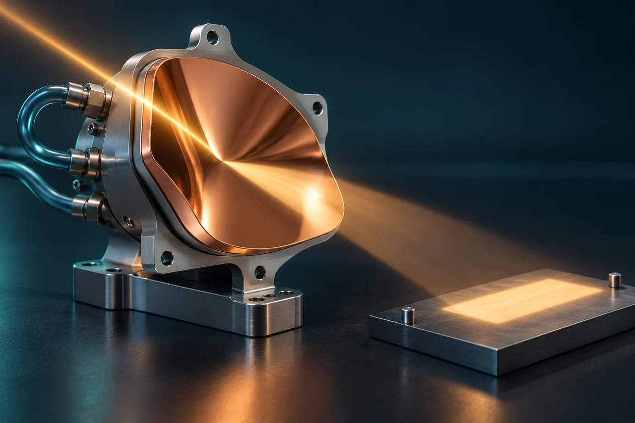
Off-axis parabolic mirror · development concept

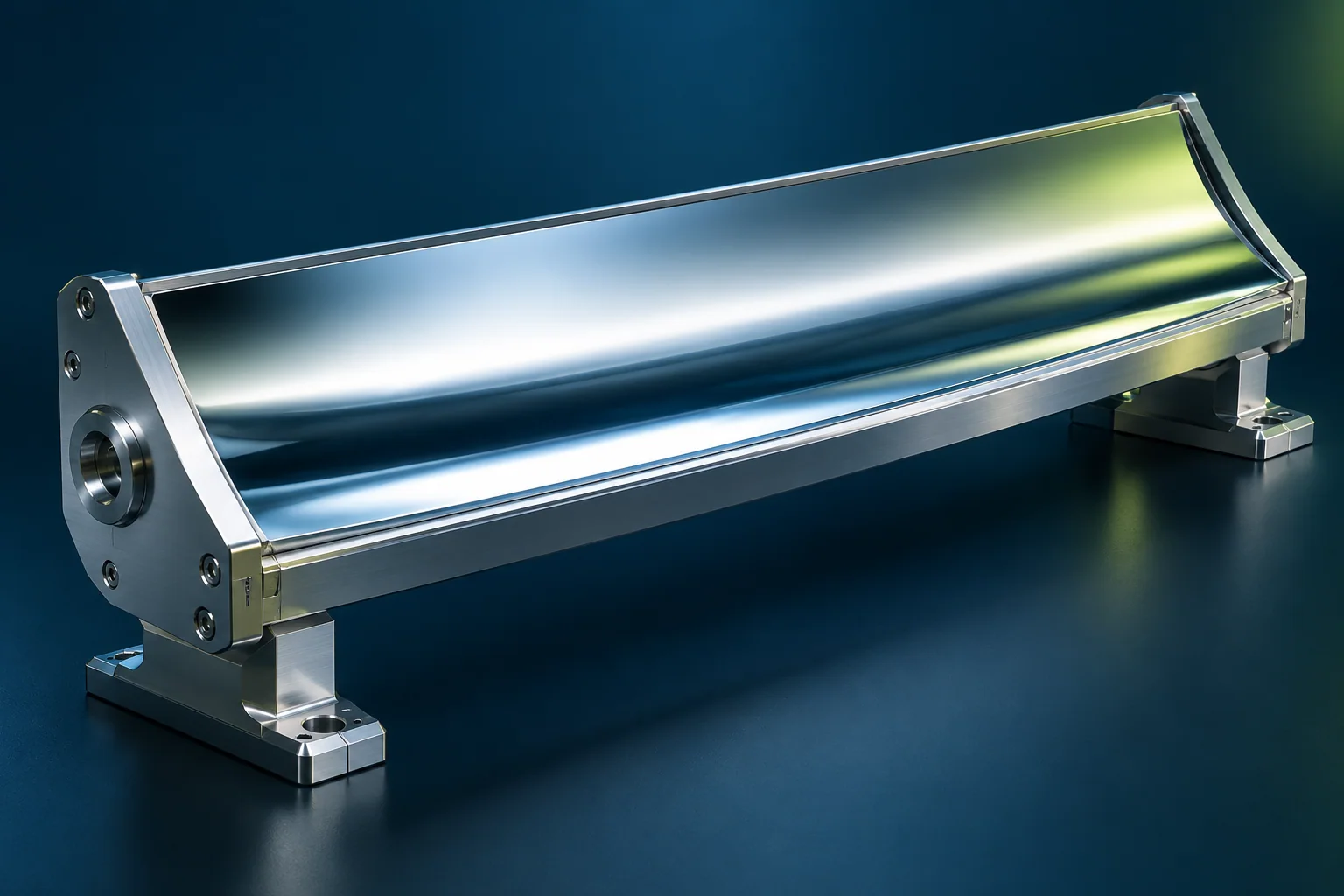
Cylindrical and toroidal mirror · development concept

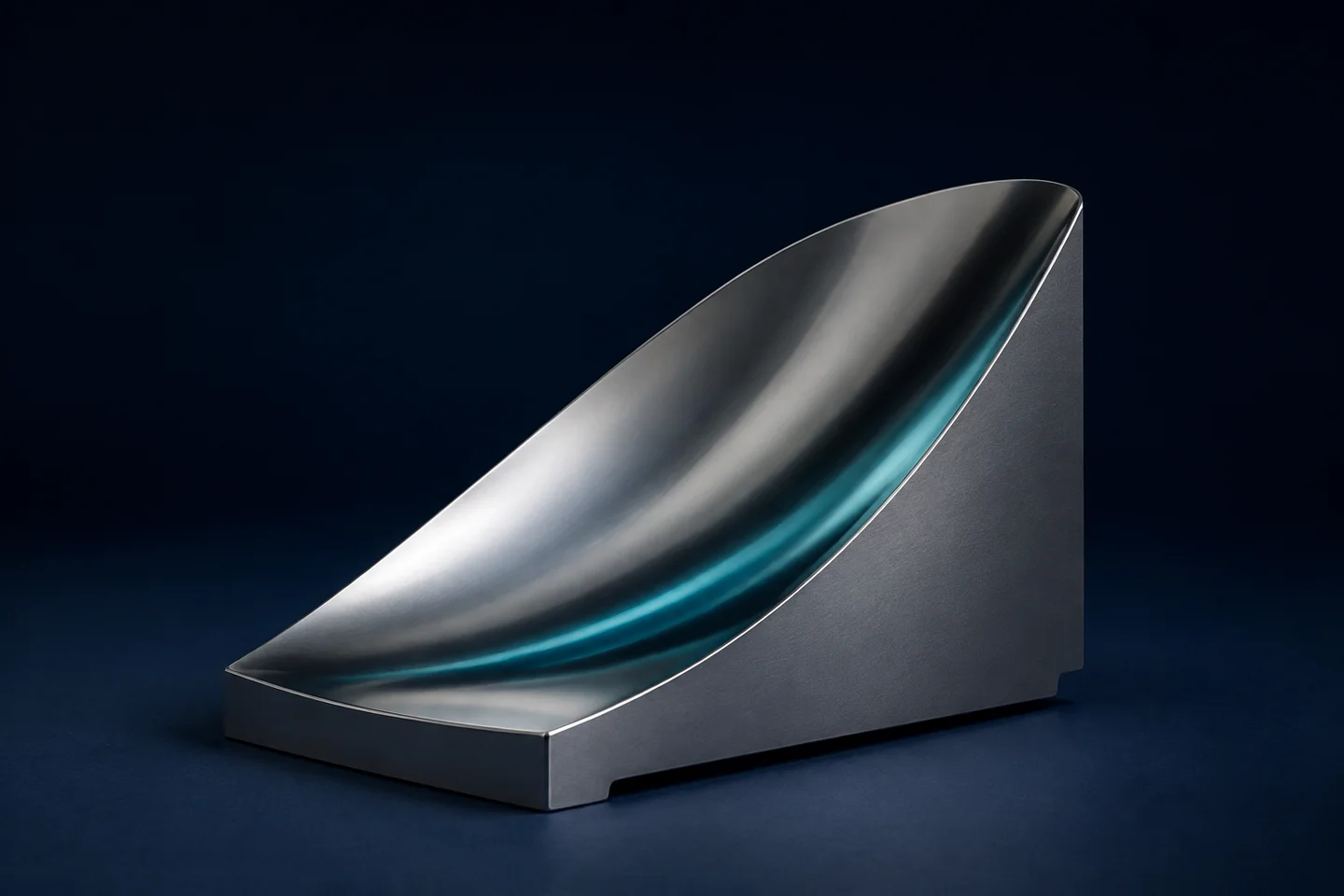
Microlens-array master · development concept

Information for a productive first discussion

Laser wavelength and operating mode; input beam size and known profile; target distribution and evaluation plane; aperture, material and mechanical interfaces; tolerances, testing needs and quantity. Without a model, a functional description can still define a useful first step.

Discuss a laser-optics task

Explore surface geometries in the 3D Surface Lab · The lab illustrates geometry; it is not a laser-optics simulation.

Application-specific development concepts

START WITH THE APPLICATION

Which surface makes the difference?

Define the function, choose the process and agree the evidence before manufacturing.

01

BEAM PROFILE · SURFACE · SYSTEM TEST

What beam distribution do you need?

The first discussion connects the required light distribution and available input beam with a manufacturable surface. The mirror, axicon or freeform element is then planned together with its inspection question.

Value: component requirements and the system test serve the same functional objective.
Define together

Wavelength, power or pulse data, input beam, target profile, aperture, mounting and acceptance criteria. The outcome is a defined trial or component task.

Your next stepDiscuss my laser-optics task

CONNECTED ENGINEERING

Different challenges. Different geometries. Shared precision.

  1. 01Function
  2. 02Geometry
  3. 03Application

Conceptual illustration of our engineering approach.

THE NEXT STEP

Let’s talk about your next component.

Tell us about its function, material and critical engineering question. Together, we can define a feasibility review or a focused first trial.

Discuss your project