
Vehicle displays · Optical tooling · 2026-10-20
Freeform replication insert for HUD optics
A non-rotational optical surface in a trial insert for HUD relay optics, with comparable evaluation of the tool and first polymer replica.
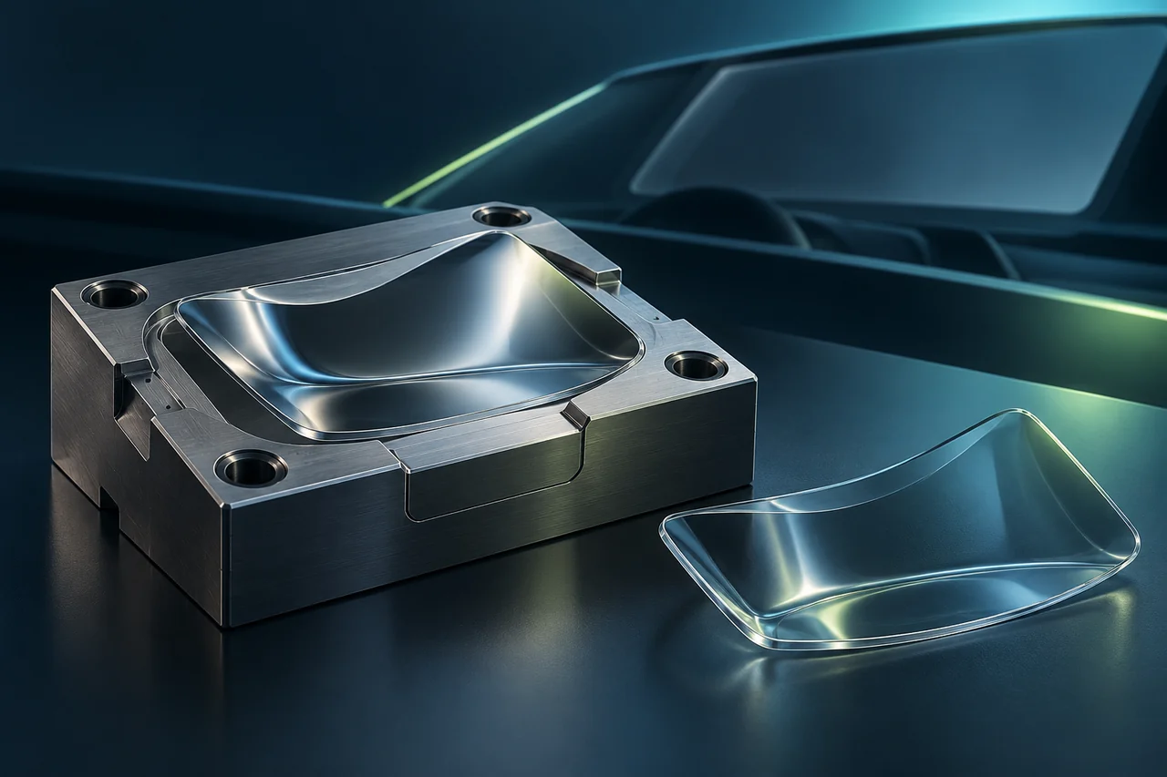
AI-generated engineering concept · Not to scale; not a manufactured component or measurement result.
FROM CONCEPT TO YOUR COMPONENT
Start with the function, material and the question your first trial should answer.
Why work with us? Make the HUD freeform assessable on a trial insert first.
A route suited to the non-axisymmetric surface
IL600 freeform machining and dynamic toolpath preparation support a trial based on the customer's surface prescription. We examine aperture, slope and tool access together.
A trial insert before full production tooling
The entry work package can be one insert and feedback from the first replication. Comparable geometric data can guide the next correction without starting a complete automotive production program at once.
Make the functional decision at system level
Delivery agreed with the optical designer and replication partner helps separate surface error from molding or assembly effects. Complete HUD image quality and automotive compliance remain separate system-level tasks.
The development gap from optical prescription to first replica
In a HUD system, relay-optic shape depends on display, windshield and intended image field. This concept uses a trial insert carrying the customer's freeform prescription. The objective is to evaluate machined surface and replication feedback in a common coordinate system.
Multi-axis access to the freeform
Once the surface equation and aperture are checked, the IL600 freeform route can be planned. Steep local regions require a separate review of tool orientation and collisions. Insert edges, fits and optical region are coordinated with the toolmaker's operation sequence.
What is compared after replication?
Evaluation compares nominal and measured insert shape, followed by agreed surface data from the polymer replica. Shrinkage compensation is not an automatic allowance; it requires knowledge of molding conditions and measurement alignment. HUD distortion, image sharpness and field of view remain part of the customer's optical system test.
Start with a trial question that can be answered
The first work package can be a critical surface region or a complete trial insert, depending on size and development objective. Machining and replication evaluations jointly determine the next step. A production mold, injection molding and end-product qualification are not automatically included in optical-insert manufacture.
What data is needed to prepare a HUD insert?
A surface equation or verified CAD data, active aperture, datums, polymer, forming process and the tool's mechanical interface are needed. Identify who owns optical design, replication and system evaluation of the finished optic. A project commitment can be defined only after these responsibilities are agreed.
For the next discussion
We scope this development route around your application.
The application behind the component.
Review the operating requirements and related engineering tasks in these application areas.
CONNECTED ENGINEERING
An idea becomes a component, step by step.
- 01Concept
- 02Prototype
- 03Evaluation
Conceptual illustration of our engineering approach.
THE NEXT STEP
Let’s talk about your next component.
Tell us about its function, material and critical engineering question. Together, we can define a feasibility review or a focused first trial.