← Applications

Optical tooling

Optical tooling

Mould and tool inserts for optical-quality surfaces, lens arrays and structured components.

Editorial insight
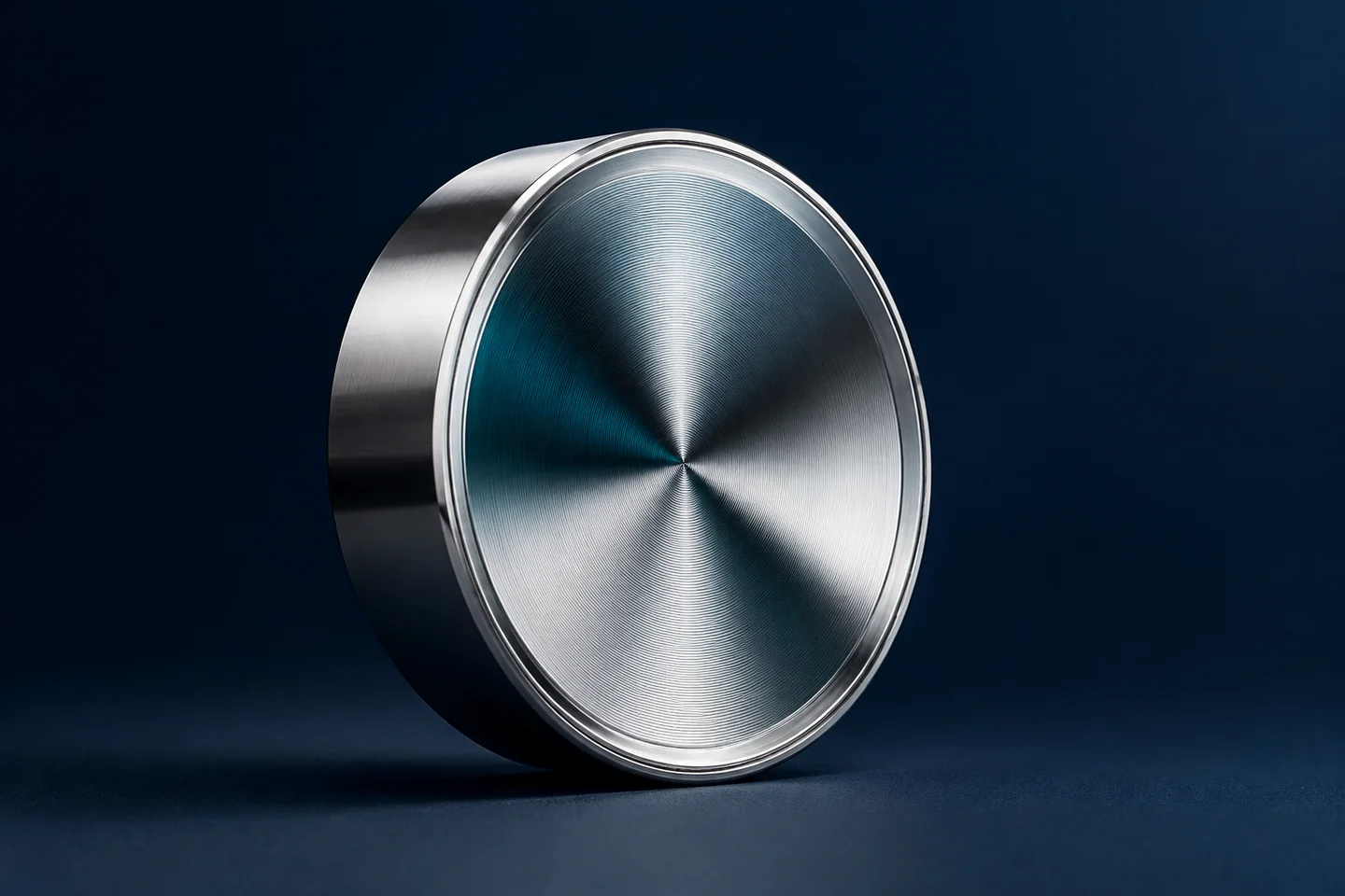
Optical tooling — illustrative visual, not measurement data

Illustrative diagram or concept image · Not a manufactured component or measurement result.

The application · transferring function through a tool

In the production of polymer optics and structured surfaces, the tool insert provides the basis for reproducing the geometry. For illumination components, imaging lenses or sensor optics, the intended light distribution and finished-part quality together define the requirement.

Potential tasks

An insert for an aspheric lens, a microlens array, a structured tool surface for a light guide or a beam-shaping surface. The task may involve a prototype insert, replication master or development variant.

We evaluate the insert as part of the complete tool and forming process. Mounting geometry around the surface, the forming direction and material selection influence the solution as much as the optical profile.

The manufacturing route

Depending on geometry, the IL600 route may involve diamond turning, freeform machining or microstructuring. Ultrasonic assistance enables assessment of additional material–process combinations. Coating selection is considered alongside replication requirements.

Substrate, surface layer and process are a shared decision. A development trial examines whether the selected route can produce the insert’s geometry and required surface characteristics.

What should be measured?

We inspect form deviation over the active optical surface, surface topography over the defined evaluation area, and datum positions within the mounting system. Inspection of the replicated part can provide further feedback for tool correction.

For the first discussion

Bring the optical surface definition, mechanical insert drawing, replication method, material and coating, active aperture and proposed inspection approach. Where no final model exists, a function-led development brief is a suitable starting point.

Further reading and a development concept

START WITH THE APPLICATION

Which surface makes the difference?

Define the function, choose the process and agree the evidence before manufacturing.

01

REPLICATION · LIGHTING · LENS ARRAYS

Plan the insert around the replicated optic.

For a lens array or light-guiding insert, the required light distribution and moulding direction define the task together. A critical feature or trial insert can be evaluated first; results from the replicated part can then guide a tooling revision.

Value: tooling development stays connected to optical performance.
Define together

Optical profile, release direction, edge radii, material/coating, moulding shrinkage and inspection of the replicated part.

Your next stepDiscuss an optical insert

CONNECTED ENGINEERING

Different challenges. Different geometries. Shared precision.

  1. 01Function
  2. 02Geometry
  3. 03Application

Conceptual illustration of our engineering approach.

THE NEXT STEP

Let’s talk about your next component.

Tell us about its function, material and critical engineering question. Together, we can define a feasibility review or a focused first trial.

Discuss your project