
Engineering guide · 2026-10-07
Freeform optics: what should accompany the CAD model?
Surface equations, coordinates, aperture and revision: checkpoints for the digital handover before machining.
Editorial insight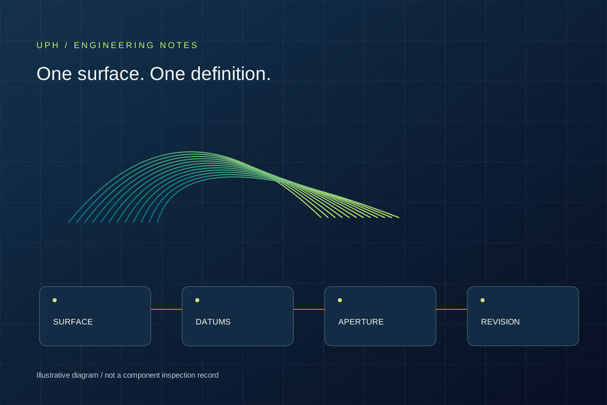
Illustrative diagram or concept image · Not a manufactured component or measurement result.
The model describes shape. The specification defines its meaning.
A smooth-looking 3D model is not sufficient to commission a freeform optical part. The optical designer, process engineer and metrologist must interpret the same nominal surface. The first question is therefore which geometry and revision are to be manufactured.
For an UPH discussion, include material grade, critical surfaces, datums and acceptance criteria alongside the model. Where equations or coefficients define the surface, supply the original definition too.
Five inputs that prevent ambiguity
Units and coordinates: dimensional units, axis directions, origin and the surface location within the optical system.
Nominal surface: equations, coefficients, domain and sign conventions, or the agreed geometric data source.
Active aperture: the region used in operation and acceptance inspection, including excluded and transition zones.
Mechanical datums: the relationship between workholding, assembly and inspection references and the optical geometry.
Revision and requirements: an identifiable file revision, its drawing and the evaluation method.
A mesh or an analytical definition?
A triangulated mesh may approximate the nominal surface. Display smoothness and geometric approximation error are different properties: a visually smooth model does not establish that the data meets the required form-error specification.
We do not automatically reject file formats. The handover is selected for the task by comparing source data, imported geometry and requirements. Without an analytical definition, agree how the surface is approximated and which deviation is acceptable.
What does multi-axis toolpath planning add?
Innolite ILCAM6DOF supports planning beyond turning kinematics, visual simulation and data analysis. This describes the platform’s software background; the UPH work plan identifies the actual preparation route for the project.
Surface access, local tool orientation, workholding and inspection access must be considered together. Simulation helps expose risks; agreed inspection establishes conformity of the completed component.
Check the handover at three stages
After import: compare units, orientation, principal dimensions and critical surfaces with the source.
Before toolpath generation: select representative regions, including steep slopes, high curvature or limited access.
Before inspection: fix the nominal surface, alignment and evaluated aperture. Workholding deformation or datum mismatch may need a different correction from a machining form error.
Can a Surface Lab model become a manufactured part?
Surface Lab’s illustrative parameters help communicate geometric intent and prepare an engineering brief. They are not manufacturing approval, validated optical design or component measurements. A quotation needs verified model data and agreed requirements.
a clear digital data package, critical regions and the questions needed for manufacturability review.
Related articles
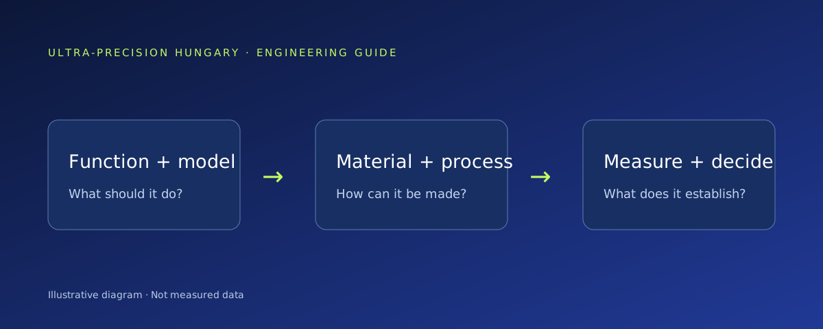 Engineering guide
2026-09-17
What makes a useful ultra-precision engineering brief?
Material condition, datums and acceptance criteria belong in the brief alongside the model.
Read article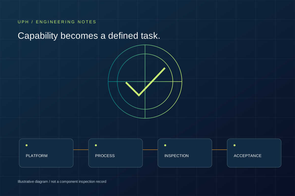 Engineering guide
2026-10-07
From the IL600 datasheet to component acceptance
What does a machine specification mean, and how does it become a clear, verifiable component requirement?
Read article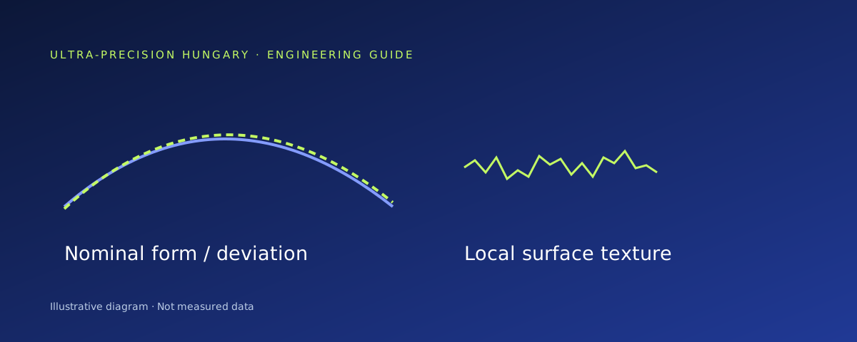 Engineering guide
2026-09-17
Surface roughness and form deviation: two different questions
A smooth surface does not necessarily follow the intended shape. Surface and geometric requirements must therefore be specified separately.
Read articleCONNECTED ENGINEERING
Details reveal the bigger picture.
- 01Question
- 02Context
- 03Insight
Conceptual illustration of our engineering approach.
THE NEXT STEP
Let’s talk about your next component.
Tell us about its function, material and critical engineering question. Together, we can define a feasibility review or a focused first trial.