
LiDAR · Mobility and industrial sensing · 2026-10-20
Freeform receiver mirror for a civil LiDAR system
An asymmetric mirror with integrated mounting for a compact receiver module, connecting light collection and assembly position in a shared feasibility trial.
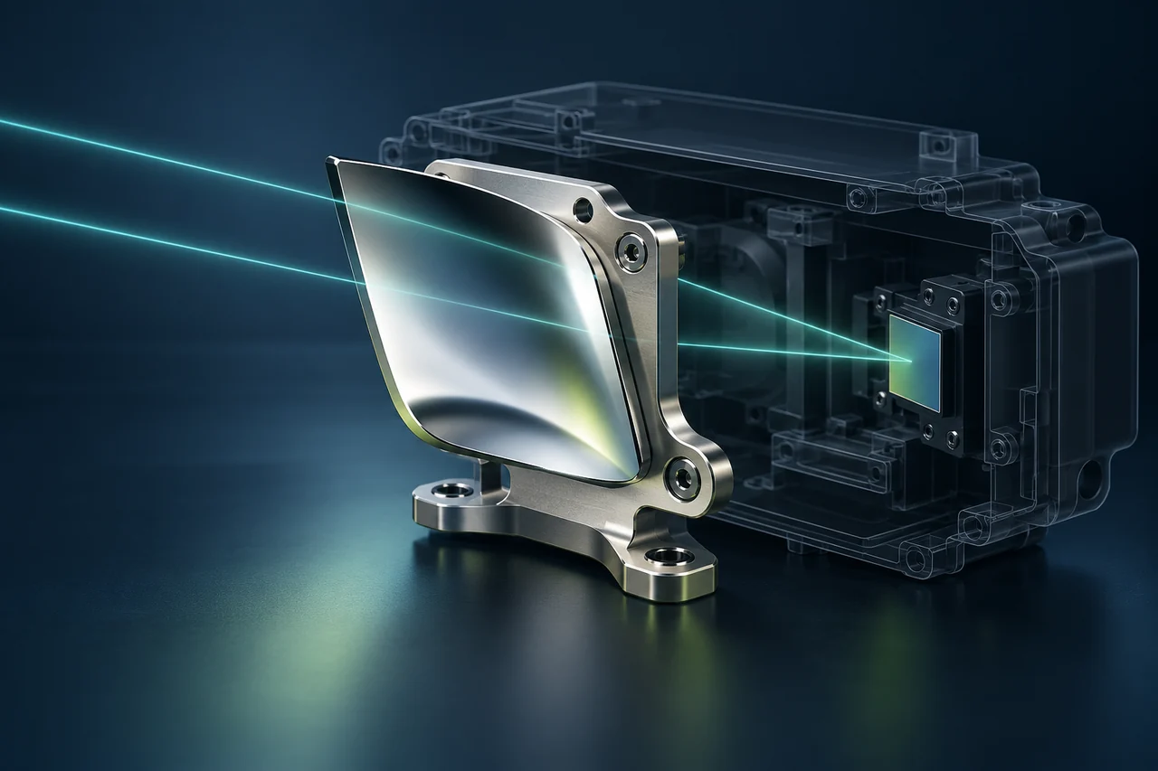
AI-generated engineering concept · Not to scale; not a manufactured component or measurement result.
FROM CONCEPT TO YOUR COMPONENT
Start with the function, material and the question your first trial should answer.
Why work with us? Address the receiver mirror and compact housing together.
A freeform surface for the available space
IL600 freeform machining suits non-axisymmetric receiver geometries. The optical surface and housing datums can be connected when planning the first component.
An informative integration trial
The first mirror can support packaging and alignment checks alongside geometric inspection. This can inform the next housing or mirror revision before committing to a production program.
A supplier relationship starting with a prototype
A custom mechanical-optical task can be particularly relevant for compact civilian sensors. Range, detection probability and environmental qualification are established in receiver-module tests; they are not automatic component guarantees.
A defined field of view within a tight package
Mobile-robot and civil ranging developments often constrain optical design through package space and detector position. This concept studies a receiver-side metal mirror whose curvature and orientation follow the customer's optical model. It does not offer a complete LiDAR unit or a guaranteed range.
Freeform optics and mechanics in one component plan
IL600 multi-axis machining and the Overdrive capability can support preparation of a non-rotational surface. Tool access, local slope and possible obscuration are reviewed before optical finishing. Workholding and the mounting flange establish an identifiable relationship between the optical surface and its installed position.
Orientation matters alongside form deviation
The acceptance plan identifies nominal surface, active aperture and position relative to mechanical datums. Wavelength-dependent coating behaviour and receiver sensitivity need separate functional tests. Point-cloud quality and system range cannot be inferred from surface roughness alone.
A pilot in the customer's optical arrangement
The first development stage can deliver an inspected mirror version and a description of workholding datums. The customer evaluates integration using its own source, detector and alignment procedure. Feedback can then inform changes to the next surface or mounting geometry.
Is this already an automotive production component?
No; the starting point is a development component. Automotive qualification, traceability and environmental requirements must be clarified separately with the customer. The brief should include wavelength, field of view, detector position, mathematical surface definition, datums and the first integration-test objective.
For the next discussion
We scope this development route around your application.
The application behind the component.
Review the operating requirements and related engineering tasks in these application areas.
CONNECTED ENGINEERING
Different challenges. Different geometries. Shared precision.
- 01Function
- 02Geometry
- 03Application
Conceptual illustration of our engineering approach.
THE NEXT STEP
Let’s talk about your next component.
Tell us about its function, material and critical engineering question. Together, we can define a feasibility review or a focused first trial.